Product Specification
| HIMALAYA MACHINERY | |
| New | |
| YES | |
| Excellent (No problems or history of failures) | |
| Gasoline |
Product Descriptions
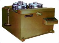
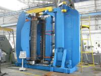
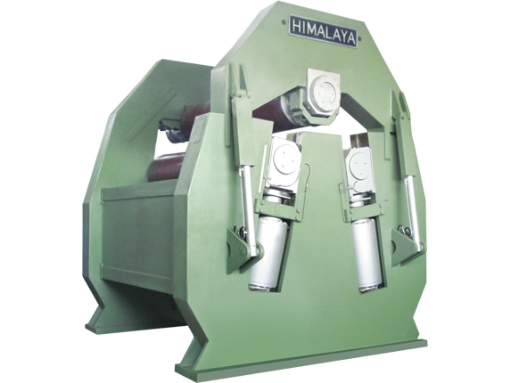
Our Plate Bending Machines deliver high performance, simplicity of design, easy installation, low-maintenance cost, greater durability and a high re-sale value.
Having an extremely long working life and high demand, our plate bending machines have received over 300 repeat orders till date.
Our quality and manufacturing excellence is displayed by the fact that the first plate bending machine which we manufactured four decades back is still functioning smoothly today.
Our Products are known for its Performance, Economy, Versatility, Reliability & Simplicity all in One
Versatile Construction, Wide Thickness Range and Time- Proven Design make 'Himalaya' Plate Bending Machines an attractive investment for any type of industry
Know your plate bending machine
It is very important to know your machine completely to use it, to maintain it and to get best performance for years to come. The machine has four major systems and they listed as follows:
1. Mechanical
2. Electrical
3. Hydraulic
4. Synchronization System (it is a combination of Elec. & Hyd. System)
The mechanical system consists of following:
1. Basic structure of the machine
2. Rolls
3. Gearboxes and its driving trains
4. Centralized Lubrication System
5. Top Roll Counter Balance System
6. Main Cylinder's Synchronizing linkages etc
The electrical system consists of following:
1. Main control panel with all electrical accessories
2. Operating Consol
3. Junction boxes
4. Different limit switches
5. Power circuits
6. Main control system
7. Hydraulic control circuits
The hydraulic system consists of following:
1. Power pack
2. Hydraulic motors
3. Valve stations
4. Main cylinders
5. Swing arm cylinder
6. Return line filter assembly
7. All inter connecting seamless and flexible pipes
By knowing the machine with its all relative systems and sub-systems, it will be very easy to handle the problem and its rectifications.
Mechanical
1) Basic structure of the machine:
Frames
The basic structure of the machine consists of two side frames and tie panels. The sides frames (HS Frame & TS Frame) are made of ultrasonically tested alloy steel plates. They are cut to their respective shapes and combined with the help of specially prepared zigs and fixtures.
They are welded under strict quality control and after full welding they are passed
through stress relieving process. All welded parts are properly ground and made free
from sharp edges. 4 nos.of main cylinders, swing arm cylinder, swing arm,
centralized lubrication pump assembly.
Harden guides, top roll supporting arrangement called counter balance system are placed in or supported by these side frames. These side frames are named as HS Frame and TS Frame. Swing arm is fixed in TS Frame or we can say that swing arm is part of TS Frame.
Tie panel
Tie panels are made of tested steel / plates and formed to required shapes. These panels are fixed with the side frames by bolts.
2) Rolls:
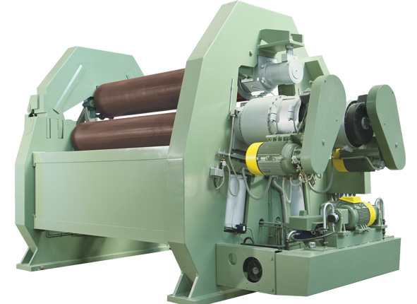
Three carbon steel forged rolls are fixed on the machine and they are known as top roll and bottom rolls.
Top roll
Machine has one Top Roller, which is supported by end bearings. These bearing are supported by two different ways in HS and TS Frames. The Top Roller is supported by the counter balance system when the swing arm is open.
Please note that the Top roller seems slightly tilted towards swing arm side in normal
condition (when no plate is feed in the machine). The Top Roll must be remaining slightly tilted towards the swing arm side for the easy movement of swing arm. This point should be kept in mind for the setting of the counter balance.
Both end bearings are lubricated by the centralized lubrication system. In normal
condition the top roller is not power driven but it rotates by the friction of the plate material. But in case of thin plate rolling the top roll drive is required and it is supplied as an optional item at extra charges. However for easy coupling of top roll drive, standard taping is inbuilt in top roll HS Side end. Detail discussion of top roll drive and its setting is done in operational manual.
Bottom roll(s)
Machine has two bottom rolls and both are power driven. These rolls are made of forged carbon steel and supported by bush bearing at both the ends.
The bearings are rest on cross guide, which is placed on top of piston rod of main cylinder. The bush material is of quality phosphorus bronze and need replacement after very long service period.
The rolls are given a special surface profile called crowning. This is discussed in the operating manual in the chapter "The Effect of Roll Deflection" in detail.
The rolls are directly coupled with the centralized lubrication system.
3) Gear boxes and its driving trains:
Plate bending machine is equipped with two planetary gearboxes to drive the bottom rolls. These gearboxes are directly coupled to bottom rolls and the complete driving train is monoblock on the machine.
The gearbox has three stages and out them two is planetary. The first stage is composed of helical gears, which is directly coupled to hydraulic motor. Next to helical stages two planetary stages are there and the final carrier (output shaft) is coupled to bottom roll.
Planetary gearbox is composed of
1. Internal gear ring which is stationary and fixed on bearing extension.
2. Planet pinions.
3. Sun pinion, which acts as input shaft for each stage.
4. Carrier of planet pinions which acts as output shaft.
5. Planet pinion pins to fix planet pinions in carrier.
All gear runs in the oil bath and recommended oil is gear oil "EP 90" or equivalent.
4) Centralized lubrication system:
Force-feed lubrication system is installed in the machine for the automatic lubrication of bearings; all six bearings are separately connected to the lubrication pump to insure prefect lubrication. The pump works on swash plate principal. A can is provided for the storage of lubricant and level rod is also provided to easy checking of lubricant level in the can.
The lubrication pump can run in two modes Manual and Automatic. The manual operating switch is on the operating console. A preset timer is provided in the electrical panel for the automatic operation of the pump. The timer works on the operating hours of the machine only.
We recommend run the pump manually for short while after long shutdown of the machine.
5) Top roll counter balancing system:
Top roll counter balancing system is very essential for the removal of the completed shell from the machine and it comes in action when the swing arm is opened and closed. To open and close the swing arm it is essential to keep the top roll floating at one end and slightly tilted also.
So to open the swing arm and to suspend the top roll in the position, it is supported from its extreme end by HS Frame. This supporting assembly is known as counter balance system. Please note that the top roll too much lower or high at swing arm side will not allow the swing arm close and a serious damage can be observed with swing arm itself of other linked items with the swing arm. A separate setting procedure is described later in information sheet no: I-9312P.
6) Main cylinder synchronizing linkages
For the precise main cylinder's movement with each other for bottom roller, synchronizing system is employed in the hydraulic system. To operate the machine efficiently it is necessary to have the cylinder movement feed back to synchronizing operating system and this feedback is provided by the linkages coupled to cylinders. One safety device is also incorporated in these linkages which stop the movement of cylinder if other cylinder is absolutely not moving.
Electrical
1) Main control panel with electrical accessories:
Following items are placed in the electrical panel:
1. Connector strip for the 415 V mains supply.
2. Main contactors for Hydraulic pump prime mover.
3. Overload protection relay for electrical motor.
4. Lubrication motor contactor with overloads protection &auto lubrication
timer.
5. Single phase prevented.
2) Operating console ( auxiliary panel):
Operating console is a portable operation station for operating the machine. Hyd. motor On & Off, right roll Up & Dn, left roll Up& Dn, S.A. (Swing Arm) Open & Close push button and lubrication manual auto mode toggle switch, Digital roll position indicator for both the roller and stop button are positioned on the panel face.
3) Junction box:
It is the interface place for the connecting the control and other supply to machine and main control panel. It is fixed on the H.S.Frame. It contains followings:
1. Terminal strips.
2. Contactors for main drives.
3. Relays for automatic loading and unloading of hydraulic system.
4. Timer for automatic loading and unloading system.
4) Different limit switches:
Many limit switches are on the machine for safety of respective components and among these the following important limit switches are listed:
1. Up limit for left and right rolls, these two limit switches placed on H.S.Frame. They prevent the excess upward travel of rolls.
2. Down limit for left and right rolls these two limit switches are placed on H.S.Frame. They prevent excess downward travel of the rolls.
3. S.A.'s locking lever-sensing switches. These limit switches are placed in S.A. Box itself.
They are safety device to prevent the rotation of rolls when the swing arm is in open condition and the locking and the looking lever is not locked in close condition.
5) Power circuits:
All mains supply for electrical motors through DOL and Star & Delta connections.
6) Main control circuits:
Control systems are for controlling of followings:
1 Main hydraulic electric motor start and stop with overload protection.
2. Lubrication motor operation in auto and manual mode with overload protection.
7) Hydraulic control circuits:
Control circuits are for controlling of followings:
1. For operation of pressure relief cum load unload valves.
2. For operation of all direction control valves for rolls up & down movements, swing arm movements etc.
3. For operation of synchronization system for left and right roll up and down movements in synchronized manner.
Hydraulic
1) Power pack:
Power pack has following:
1. Hyd.oil reservoir, a fabricated tank can be opened from the top and having air breathers, level switch with visual level indicator, temp., indicator and drain plug.
2. Hydraulic pumps coupled with electric motor.
3. Hyd. Oil cooling system with radiators and independent oil circulation pump.
4. Strainers are fitted on suction line of the main pumps.
2) Hydraulic motors (Directly coupled to planetary gear boxes) :
3) Valve satiations:
Different valve stations are mounted on frame for direction control valves of main drive, main cylinders up and dn. movements, swing arm open and close operation, relief cum loading unloading valve and main cylinder's annular port pressure control valve. Loading and unloading of hydraulic system on this machine is automatic to prolong the life of hydraulic components.
As any operation is activated, the system mode changes from unload to load and required pressure will be developed automatically and if the machine is idle for some time it will automatically switched to unload mode.
This is very unique future of the system for prolongs life of hydraulic components and hydraulic oil.
4) Main cylinders:
There are 4 nos. of double acting main cylinder for bottom rolls up and down movement. The bottom inlet / outlet port directly connected to pilot operated check valve for better safety.
The annular port of these cylinders is feed system oil through PCR valves. These PCR valves feed system oil at lower pressure. This future is very essential for smooth lowering
5) Swing arm cylinder:
One double acting cylinder for swing arm operation.
6) Return filter assembly:
Full flow return line filters with inbuilt check valve for safety against jamming.
7) All interconnecting seamless pipelines and flexible hoses:
All hydraulic operating applications are connected with seamless pipelines and flexible hoses with necessary "o" ring and fittings.



 Safe and secure payments using Abraa safe trade systems
  \
\
